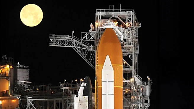




Space Shuttle Discovery, like its sister orbiters, represented a pinnacle of aerospace engineering, combining the capabilities of a spacecraft with the aerodynamic characteristics of an aircraft. Its design was a complex interplay of structural integrity, advanced propulsion, sophisticated control systems, and life support, all meticulously crafted to enable repeated journeys to and from low Earth orbit. Understanding the intricate details of its construction
and operational systems provides insight into the challenges and triumphs of the Space Shuttle program.
Structural Composition and Aerodynamic Form
The orbiter's primary structure was composed mainly of aluminum alloy, a material chosen for its strength-to-weight ratio. However, in later orbiters such as Discovery, Atlantis, and Endeavour, engineers incorporated graphite epoxy in some structural elements to further reduce weight, demonstrating a continuous effort to optimize performance. The engine thrust structure, a critical component subjected to immense forces, was constructed from titanium alloy, known for its high strength and resistance to extreme temperatures. The windows, vital for crew visibility and protection, were a composite of aluminum silicate glass and fused silica glass, featuring an internal pressure pane, a 1.3-inch-thick optical pane, and an external thermal pane, all tinted with the same ink used for American banknotes.Aesthetically, the Space Shuttle orbiter resembled an airplane, a design choice that facilitated its atmospheric re-entry and landing. It featured a standard fuselage and two double delta wings, swept at an angle of 81 degrees at their inner leading edges and 45 degrees at their outer leading edges. The vertical stabilizer had a leading edge swept back at a 45-degree angle. Control surfaces included four elevons on the trailing edges of the delta wings and a combined rudder and speed brake on the vertical stabilizer. A movable body flap located beneath the main engines further aided in controlling the orbiter during the later stages of re-entry.
Propulsion and Attitude Control Systems
At the heart of the orbiter's maneuverability was its Reaction Control System (RCS), a sophisticated network of 44 small liquid-fueled rocket thrusters. This fly-by-wire flight control system employed computationally intensive digital Kalman filtering to manage attitude control along the pitch, roll, and yaw axes throughout all flight phases: launch, orbiting, and re-entry. Beyond mere attitude adjustments, the RCS also executed orbital maneuvers, including changes in altitude, orbital plane, and eccentricity, which demanded greater thrust and impulse.The RCS was strategically distributed across the orbiter. The forward rockets, located near the nose, included 14 primary and two vernier RCS rockets. The aft RCS engines were housed within the two Orbital Maneuvering System (OMS) pods at the rear, each containing 12 primary (PRCS) and two vernier (VRCS) engines. The PRCS provided the primary pointing control, while the VRCS was crucial for fine maneuvering during rendezvous, docking, and undocking operations with the International Space Station or the Mir space station. The propellants used, monomethyl hydrazine (fuel) and dinitrogen tetroxide (oxidizer), were hypergolic, meaning they ignited spontaneously on contact, allowing for easy starting and restarting without an ignition source—an ideal characteristic for spacecraft maneuvering systems.
Crew Accommodations and Power Generation
The pressurized cabin of the orbiter was a meticulously designed environment for the crew. The flight deck, or cockpit, was equipped with an astonishing 2,214 controls and displays, a testament to the complexity of operating the vehicle. The commander and pilot occupied fixed seats on the flight deck, with up to two mission specialists seated behind them in stowable seats. Below the flight deck was the mid-deck, which could accommodate additional stowable seats depending on mission requirements. This area also contained essential facilities such as the galley, toilet, sleep locations, storage lockers, and the side hatch. An airlock on the mid-deck provided a crucial interface to the payload bay, allowing astronauts in Extravehicular Mobility Unit (EMU) space suits to depressurize for spacewalks and safely re-enter.Electrical power for the orbiter's myriad subsystems was supplied by a set of three hydrogen-oxygen fuel cells. These cells generated 28-volt DC power, which was also converted to 115-volt 400 Hz AC three-phase electric power for systems requiring it. These fuel cells provided power to the entire Shuttle stack from T-minus 3 minutes 30 seconds until the mission's conclusion. The cryogenic hydrogen and oxygen needed for the fuel cells were stored in tanks within the mid-fuselage, with the number of tank sets adjustable based on mission duration and power demands. Each fuel cell could continuously generate 21 kilowatts of power, with a 15-minute peak of 36 kilowatts, while the orbiter typically consumed about 14 kilowatts, leaving a significant margin for payload power. A beneficial byproduct of this power generation was potable water for the crew.